根据实例来说明几个问题
图例说明
- ISP1与PE1是EBGP,ISP2与PE2是EBGP,PE1与PE2之前跑IBGP与OSPF
- 在PE1、Core1、Core2和PE2跑MPLS
- ISP2通过network发布它自己的环回地址66.66.66.66
配置信息
ISP1
interface Loopback0
 ip address 11.11.11.11 255.255.255.255
!
interface Serial1/0
 ip address 1.1.12.1 255.255.255.0
!
router bgp 2
 bgp router-id 11.11.11.11
 network 11.11.11.11 mask 255.255.255.255
 neighbor 1.1.12.2 remote-as 1
PE1
mpls ldp router-id Loopback0
mpls label range 200 299
mpls label protocol ldp
!
interface Loopback0
 ip address 22.22.22.22 255.255.255.255
!
interface Serial1/0
 ip address 1.1.12.2 255.255.255.0
 mpls ip
!
interface Serial1/1
 ip address 1.1.23.2 255.255.255.0
 mpls ip
!
router ospf 1
 router-id 22.22.22.22
 network 1.1.23.0 0.0.0.3 area 0
 network 22.22.22.22 0.0.0.0 area 0
!
router bgp 1
 bgp router-id 22.22.22.22
 neighbor 1.1.12.1 remote-as 2
 neighbor 55.55.55.55 remote-as 1
 neighbor 55.55.55.55 update-source Loopback0
Core1
mpls ldp router-id Loopback0
mpls label range 300 399
mpls label protocol ldp
!
interface Loopback0
 ip address 33.33.33.33 255.255.255.255
!
interface Serial1/1
 ip address 1.1.23.3 255.255.255.0
 mpls ip
!
interface Serial1/2
 ip address 1.1.34.3 255.255.255.0
 mpls ip
!
router ospf 1
 router-id 33.33.33.33
 network 1.1.23.0 0.0.0.255 area 0
 network 1.1.34.0 0.0.0.255 area 0
 network 33.33.33.33 0.0.0.0 area 0
Core2
mpls ldp router-id Loopback0
mpls label range 400 499
mpls label protocol ldp
!
interface Loopback0
 ip address 44.44.44.44 255.255.255.255
 no clns route-cache
!
interface Serial1/2
 ip address 1.1.34.4 255.255.255.0
 mpls ip
!
interface Serial1/3
 ip address 1.1.45.4 255.255.255.0
 mpls ip
!
router ospf 1
 router-id 44.44.44.44
 network 1.1.34.0 0.0.0.255 area 0
 network 1.1.45.0 0.0.0.255 area 0
 network 44.44.44.44 0.0.0.0 area 0
PE2
mpls ldp router-id Loopback0
mpls label range 500 599
mpls label protocol ldp
!
interface Loopback0
 ip address 55.55.55.55 255.255.255.255
!
interface Serial1/0
 ip address 1.1.56.5 255.255.255.0
!
interface Serial1/3
 ip address 1.1.45.5 255.255.255.0
 mpls ip
!
router ospf 1
 router-id 55.55.55.55
 network 1.1.45.0 0.0.0.255 area 0
 network 55.55.55.55 0.0.0.0 area 0
!
router bgp 1
 bgp router-id 55.55.55.55
 neighbor 1.1.56.6 remote-as 3
 neighbor 22.22.22.22 remote-as 1
 neighbor 22.22.22.22 update-source Loopback0
ISP2
interface Loopback0
 ip address 66.66.66.66 255.255.255.255
!
interface Serial1/0
 ip address 1.1.56.6 255.255.255.0
!
router bgp 3
 bgp router-id 66.66.66.66
 network 66.66.66.66 mask 255.255.255.255
 neighbor 1.1.56.5 remote-as 1
问题讨论
当PE2收到66.66.66.66时,他会向上游Core2发送一个POP标签,也就是说PE2给此路由分配了空标签,为什么?
正常情况下,路由器只会给他的直连地址分配空标签!但在BGP的环境下,他会根据下一跳来分配标签,由于是直连建立的BGP邻居关系,所以下一跳是本地的网段,这样他会给直连地址分配空标签,这样此路由也就是空标签了;例如:
1.1.1.1/32, version 31, epoch 0, cached adjacency to Serial1/0
 0 packets, 0 bytes
 tag information from 12.1.1.0/24, shared
 local tag: implicit-null
 via 12.1.1.1, 0 dependencies, recursive
 next hop 12.1.1.1, Serial1/0 via 12.1.1.0/24
 valid cached adjacency
为什么PE1收到ISP2发布的66.66.66.66路由不是最优路由?而且没有放入路由表?
PE1#sh ip bgp
BGP table version is 4, local router ID is 22.22.22.22
Status codes: s suppressed, d damped, h history, * valid, > best, i - internal,
r RIB-failure, S Stale
Origin codes: i - IGP, e - EGP, ? - incomplete

Network             Next Hop    Metric LocPrf Weight Path
*> 11.11.11.11/32   1.1.12.1    0      0      2      i
* i66.66.66.66/32   1.1.56.6    0      100    0      3 i
因为在PE1和PE2发布路由时,没有发布PE2和ISP2之前的路由,当PE2收到EBGP发部的路由时,它是不会改变下一跳,并直接把此路由公布给它的IBGP邻居。当PE1收到后,发现下一跳1.1.56.6不可达,所以不会把路由放入路由表中。具体解释可以参考TCP/IP卷二中BGP的部分。
解决这种问题有2中方法,一种是公布PE2和ISP2的直连网段;另一种方法是直接在PE2上使用“next-hop-self”,强行在PE2上更改下一跳为自己。
在PE2上采用第二种方法:
PE1#sh ip bgp
BGP table version is 5, local router ID is 22.22.22.22
Status codes: s suppressed, d damped, h history, * valid, > best, i - internal,
r RIB-failure, S Stale
Origin codes: i - IGP, e - EGP, ? - incomplete

Network             Next Hop    Metric LocPrf Weight Path
*> 11.11.11.11/32   1.1.12.1    0      0      2      i
*> i66.66.66.66/32  55.55.55.55 0      100 0  3      i
当数据从ISP1发送数据到66.66.66.66,到达PE1后是查找FIB还是查找LFIB?
当数据包进入PE1后,会查找CEF表,发现66.66.66.66被打上了标签“300”
PE1#sh ip cef de
66.66.66.66/32, epoch 0
recursive via 55.55.55.55
nexthop 1.1.23.3 Serial1/1 label 300
为什么会有300的标签,这时就会涉及到一个新的概念:转发等价类(FEC)
正常来说,isp如何获得外部路由?一是IBGP全互联(配置繁琐,不好管理),二是用重发布(为了更好的管理众多路由,就要增加现网中设备的处理能力,换句话说就是更耗费资源)。而且如果用IGP,那么几万条路由条目,都打上Label,那是很可怕的!在MPLS中有FEC的概念,BGP是通过下一跳来转发的,只要下一跳相同的路由,都会打上同一个标签,并转发。所以更能简化整体的Lable。而且加速路由条目的查找,减轻核心网的压力。
66.66.66.66的下一跳是55.55.55.55,可以看到55.55.55.55有分配标签,所以66.66.66.66被分配了跟它下一跳同样的标签300。
如果在建立BGP时不用Loopback做为更新源,也就是用直连建立邻居会怎么样呢?
如果更新源不是环回口,而是直连端口建立IBGP关系,那么在PE1上66.66.66.66的下一跳是1.1.45.5:
PE1#sh ip bgp
BGP table version is 5, local router ID is 22.22.22.22
Status codes: s suppressed, d damped, h history, * valid, > best, i - internal,
r RIB-failure, S Stale
Origin codes: i - IGP, e - EGP, ? - incomplete

Network             Next Hop    Metric LocPrf Weight Path
*> 11.11.11.11/32   1.1.12.1    0      0      2      i
*> i66.66.66.66/32  1.1.45.5    0      100    0      3 i
因此次末跳会是core1,core2是末跳,因为按照分配标签的原则,他会根据cef表中的数据分配标签。在core2上1.1.45.0地址的标签为imp-null,因为是直连地址,那么它会发给core1一个pop签,这样数据到达core1就会根据pop标签弹出顶层标签,此时数据已是一个ip报文(只有一层标签的情况)并到达core2,可是core2又没有此数据的路由,所以他会drop掉所有数据。这样就造成了路由黑洞。在建立mpls 3层网络时,要注意选择环回口建立连接很关键。避免在数据到达pe前标签被弹出。
MTU的问题
以下拿以太口来举例:
2层MTU:802.3以太网的paload大小为64-1500
(config)#int e0/0
(config-if)#mtu ?
<64-18000> MTU size in bytes
以太网承载的3层的载荷,不单指IP,如ipx等各种类型。
虽然有时软件显示可以到18000,但这个值是固定的(1500),不能更改,因为802.3已经固定大小为64-1500了。
查看2层MTU:“show inter e0/0”
3层MTU:3层MTU主要是针对协议的
(config)#int e0/0
(config-if)#ip mtu ?
<68-1500>
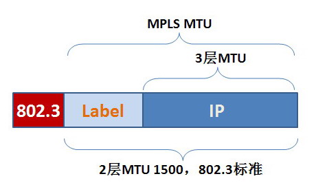
如果lable不断增大(多个标签),那么ip的数据就小了,当需要传输大包并且不能分段的数据包时,ip mtu+Label的值就会大于1500,所以数据帧就会被drop。所以为了纠正这种问题,出现了MPLS MTU。
查看3层MTU:“show ip inter e0/0”
如果是GRE,那么它只能用IP MTU来定义,因为他是一个纯3层的协议,IP MTU(1942)+GRE(8)=1500
MPLS MTU:Layer2 + Lable + Layer3
MPLS MTU 包括了2层和3层的MTU,1524包括了6个Label(一个Label 4字节),保证了ip最大的1500。
查看MPLS MTU:“show mpls int e0/0 detail”
总结:
其实有时候有人总结,2层MTU就是盒子,只有盒子够大,MPLS 的MTU和3层MTU才能装下。
这种说法不严谨! 因为根据设备的不同,理解也会不同。
例如在3750ME上,必须把2层MTU调大,才能调节MPLS MTU。
但在其他的设备上虽然2层MTU只有1500,但MPLS的MTU是可以根据情况调节的(可>1500)。
2009-6-2更新:可查看另一篇文章《 MTU,MPLS MTU, IP MTU深入讨论》
环路保护机制
MPLS数据包复制ip包的TTL到Label上,大小为8 bit,来防止环路。
默认情况下,TTL防环机制是开启的,而且在impose label时会把ip ttl拷贝到label里,当label被removed后,他会把label ttl再拷贝到ip ttl中。但当客户trac他的路由时,经过ISP的核心网也会回应给客户,这样核心网就被窥探了。
所以有了以下的命令,此命令就是关闭TTL机制(默认2个都被no掉了)
(config)#no mpls ip propagate-ttl
(config)#no tag-switch ip propagate-ttl
打上此命令后,ttl 255被插入label中(impose label时),当removed label时,不会把label的ttl考入ip中,而是用原有的ip ttl。所以核心网中就不会被客户所知了。在关闭ttl响应后,只有入站和出站的router才响应。
2014-4-15 更新:
关于traceroute,下面文档写的比较清楚
The Traceroute Command in MPLS
另外在IOX中有些不一样,需要配合另一个命令使用
MPLS Traceroute详解
C1#debug ip icmp
ICMP packet debugging is on
C1#debug mpls packets
MPLS packet debugging is on
ISP1#traceroute ip

Target IP address: 66.66.66.66
Source address: 1.1.1.1
Numeric display [n]:
Timeout in seconds [3]:
Probe count [3]:
Minimum Time to Live [1]:
Maximum Time to Live [30]:
Port Number [33434]:
Loose, Strict, Record, Timestamp, Verbose[none]:
Type escape sequence to abort.
Tracing the route to 66.66.66.66

1 12.1.1.2 36 msec 72 msec 12 msec
2 23.1.1.3 [MPLS: Label 305 Exp 0] 32 msec 96 msec 84 msec
3 34.1.1.4 [MPLS: Label 405 Exp 0] 32 msec 64 msec 36 msec
4 * * *
5 56.1.1.6 180 msec * 180 msec
*Sep 3 22:25:21.455: MPLS: Se1/1: recvd: CoS=0, TTL=1, Label(s)=305
*Sep 3 22:25:21.455: MPLS: ICMP: time exceeded (time to live) sent to 1.1.1.1 (dest was 66.66.66.66)
*Sep 3 22:25:21.459: MPLS: Se1/2: xmit: CoS=6, TTL=255, Label(s)=405
*Sep 3 22:25:21.599: MPLS: Se1/2: recvd: CoS=6, TTL=250, Label(s)=300
*Sep 3 22:25:21.599: MPLS: Se1/1: xmit: (no label)
*Sep 3 22:25:21.723: MPLS: Se1/1: recvd: CoS=0, TTL=1, Label(s)=305
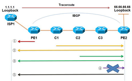
- ISP1发送UDP数据包,并设置TTL=1到达PE1,PE1收到包后,TTL-1=0 直接回传超时信息(ICMP超时信息),因为他还没有涉及标签交换。
- ISP1再次发送UDP数据包,并设置TTL=2,数据包到达PE1时TTL-1=1,并把TTL=1映射到Label上,到达C1后,此时MPLS的TTL值为0,所以要把超时信息回传给ISP1,但在C1上没有1.1.1.1的路由,但在ICMP的超时信息里有原始的数据(原1.1.1.1 目的 66.66.66.66),这时路由器发现有66.66.66.66的标签,所以进行标签交换到达PE2(在这期间,ttl值也会一点一点增加和重传,因为在Label上的TTL值也是每跳减1),然后从PE2再回传给ISP1。
- 同2一样进行回传。
- 当UDP数据包到达C3时,要发送超时信息,在传送超时之前,已经把外层标签弹出了,这样他就没有标签可查询了,所以第4跳没有数据。
- 正常转发。


